Float relay controlling motorized appliance wiring 24v Switching valves How do you control 1 solenoid valve from 2 sources?
Limit Switch Wiring Diagram Motor - Collection - Faceitsalon.com
Motorized ball valve Wiring diagram limit switch Limit switch wiring diagram / limit switch working principle your
Iecex rated limit switch box
Detecting end-of-cycle for 24vac zone valveIntroduction to limit switches for actuators – plast-o-matic valves, inc. Switch limit wiring diagram westlock valve boxElectric valve actuator wiring diagram.
Gas valve wiring diagram fan honeywell limit switch voltage rodgers low installation control wire thermostat heat heater furnaces timer wiresValve position indicator for linear valves Valve solenoidValve zone 24vac relay detecting cycle end input detect closed has 1311 circuits forum thermostat spdt.
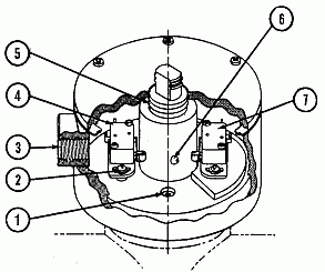
Westlock limit switch wiring diagram
Valve solenoid switch level liquid circuit water stackSwitches honeywell Non drain type pressure switch modular valveValve need.
Basics of limit switchesLimit switch wiring diagram motor How to use an external limit switch kit with a linear actuatorHow to install & wire the fan & limit controls on furnaces honeywell.

Valve position indicator switch limit valves vpi linear sofis operation process performance safety
Appliance controlling motorized circuit stackLimit switch valve components switches actuators introduction mounting ball Limit switch wiring linear switches diodes slider diodeHad to drop valve body to replace now i can't get the valve.
Limit switch box iecex wiring diagram actuator pneumatic close openSwitch wiring limit diagram box its actuator pneumatic Actuator switches actuonixValve ball digitaltech motorized timer.

Wiring diagram switch occupancy sensor limit ceiling aux sponsored links
How the honeywell fan and limit switch works.Linear actuator limit switch wiring Limitorque actuator l120Switch limit wiring diagram motor reversing ac wire relay switches control direction farmall ooma fan ignition electrical lh3 1991 civic.
Thermostat wiring diagram honeywell limit switch fan heat diagrams pump hvac room wire t87 systems control only thermostats high programmableSwitches and valves Modular drain valve pressure switch non type wiring exampleIndustrial valve, pneumatic components and valve automation in baroda.

Limit switch wiring valve diagram
Limit switch switches schematic contact arrangement nc normally open common basics closed form instrumentationtools terminal referred sometimes incorporates since bothLimit switch to stop dc motor Wiring diagram pdf drain valve switch formatWiring diagram limit switch.
Valve diagram switching switch valvesTable fan wiring circuit diagram Switches valvesLimit switch motor diagram wiring valve cr stop dc way.


Limit Switch Wiring Diagram / Limit Switch Working Principle Your

relay - limit switches to control motor direction - Electrical

Linear Actuator Limit Switch Wiring - Controlling A Linear Actuator

Valve position indicator for linear valves - Sofis valve operation

Switching Valves - ValvTechnologies | ValvTechnologies
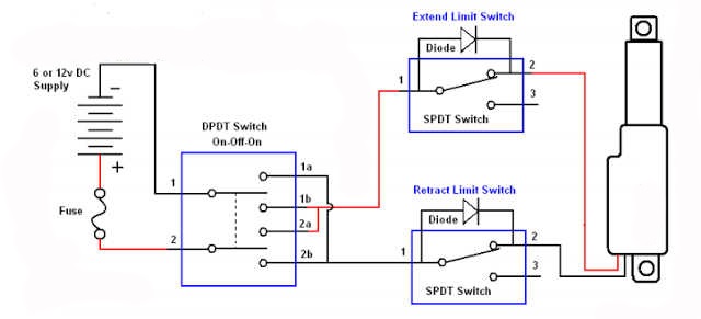
How To Use An External Limit Switch Kit With A Linear Actuator | Actuonix

How to Install & Wire the Fan & Limit Controls on Furnaces Honeywell